|
|||
|
|
|
||
| View Shopping Cart |
| Home |
| Guides Available |
| About the Author |
| FAQs |
| Testimonials |
| Articles |
| Contact Andrew |
| Terms & Conditions |
| Mailing List |
| Links |
 |
 |
Get more great articles with every issue of Successful Electrics, the free magazine from Gibbs Guides
Learn more!
ARF Hangar 9 P51 D
Electric conversion project
Part 1 - The Electric Power System
by Andrew Gibbs
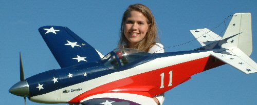
The North American P51 Mustang is such a well known WW2 warbird that it hardly needs any introduction. However, it is perhaps not so well known that WW2 warbirds are still used for air racing. Perhaps the most famous racing P51 is a modified example known as Miss America. This aircraft flew at Reno for many years in its distinctive red white and blue colour scheme. This prototype certainly makes for an interesting alternative to the usual military schemes.
The most obvious of the exterior modifications made to the real aircraft include the removal of weapons and the addition of a distinctive red, white and blue colour scheme. Hangar 9’s model is a well-executed semi-scale representation of the full-size subject. In contrast to some Mustang models, this one captures the essence of the full size one quite well.
The building process was pretty straightforward, and as the vast majority of the work in this project went into the conversion to electric power, I’ll concentrate of describing the process.
|
|


The wings
It quickly became clear that all of the work necessary
for conversion to electric power would involve the fuselage.
While I was thinking about the necessary modifications,
the wings were assembled. This was a straightforward task,
and the only problem I encountered was with the retract
units. These were supplied ready-installed, but one of
the legs was found to be loose and rotated in its mounting
block. This was later traced to a loose fixing screw which
was easily remedied, but not before I had spent time investigating
how the unit was put together.
The model is supplied with pre-fitted mechanical retracts. The instructions detail the builder to install the retract servo leaving the operating rods in their supplied straight condition. This would have caused the rods to foul each other, which would have resulted in a stalled retract servo. Since a stalled servo will flatten a battery quite quickly, this is not something that can be ignored.
Fortunately it was a simple matter to bend the rods so that no fouling occurred. This sort of knowledge is commonplace among more experienced modellers, but it may not be obvious to the pilot brought up on a diet of fixed-gear ARFs and I feel the instructions could have addressed this point.
The electric conversion
When converting a model of this size to electric power,
there is a bit more to consider than there is with smaller
models. The power system need to be considered, but so
also does the way the RC system will be powered. More
on this later.
Choosing the power system
Choosing an electric power system for a new model is often
a cause for some angst, as there are so many variables
to consider. Fortunately, this process is now made very
easy in the guide Power
System Solutions. After a couple of
quick preparatory steps to decide how much power is required
(guidance provided) a combination of suitable components
can quickly be identified using the quick reference tables
which comprise the bulk of this guide.
For this model, a 950 Watt system was decided on. The relevant table, extracted from the guide Power System Solutions is shown below:
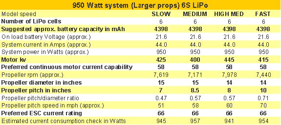
The 'medium' and 'fast' columns show that a motor with a Kv between 400 and 415 Kv would be suitable for this model. Taking the 'medium' column, we can see that the basis of the suggested power system is a 6S LiPo supplying a current of 44 Amps. The table suggests that a list of suitable power system components would be as follows:
- A 6S LiPo, approx 4,400 mAh in capacity
- A brushless outrunner with a Kv of 400, preferably capable of at least 58 Amps continuously.
- A 15 x 8.5 prop
- An ESC rated at 66 Amps or more.
For this model, I used an EFlite Power 60 motor (Kv = 400) and a 6S 5,000 mAh LiPo. A 70 A ESC provided control.
| The guide 'Power System Solutions' suggests a 400 Kv motor such as this one would be suitable for this model. This example is supplied with a prop adapter and ready fitted connectors | This 6S 5,000 mAh LiPo is slightly larger than the battery suggested in the guide 'Power System Solutions'. A slightly smaller capacity battery than suggested could also have been used. |


Fitting the motor
The brushless outrunner was quite a bit shorter than the
combined length of an equivalent i.c. (gas) engine and
engine mount. This meant that the motor would have to
be spaced forward from from the firewall. A commercial
motor mount could have been used for this, but I decided
to accomplish this by means of a simple plywood spacer
box.
To determine the dimensions for this box, I first fitted the cowl in place and then measured the distance from the firewall to the front of the cowl. It was them a simple matter to design the 4mm plywood spacer box on which the motor would be mounted. I was out of stock of plywood, so a new Ikea magazine rack made from good quality 4 mm plywood was sacrificed for the project!
The depth of the box was made so that when the the motor was screwed to it, the propeller driver would be correctly positioned. I made the box very slightly under sized, and planned to add shims between the motor and the spacer box so that the resulting prop driver position could be adjusted to the exact position required. The spacer box did not require any side thrust to be built in, as the existing firewall already incorporated this.
The spacer box was then glued to the firewall using an epoxy adhesive, and the motor bolted in position. For additional joint strength, the gluing area was increased by using triangular balsa fillets.
|
5 Although not
essential, the spacer box was lightened with a few
holes. Motor mounting was simple using the supplied
radial mount. |
6 I added balsa to the back of the spacer box to increase the glued area. |


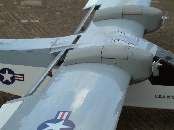
| 7 The two holes at the top of the square battery tube allow cooling air to exit. | 8 This access hole was cut into the forward decking of the fuselage to accept the battery tube. There was no going back now! |


Battery access and installation
The arrangements for accommodating the 5,000 mAh LiPo
battery had to be carefully thought out. Because of the
possibility of a fire due to a charging accident, lithium
batteries must always be removed from a model before recharging.
It would have been possible to install a simple battery mounting plate within the fuselage, and to simply strap the battery to that. However, this arrangement would have meant removing the wings each time the battery needed to be accessed for charging, which was an inconvenience I did not want to put up with.
It was also necessary to consider the effect on the balance point of the model as a result of the chosen battery location. Battery cooling was another issue that needed thinking about, and a method also had to be devised of restraining the battery against flight loads.
After some thought, I decided that battery access would be through a hatch in the forward fuselage, into a forward sloping battery box. This would make the battery easy to remove for recharging purposes. By temporarily taping the various power system and RC system components in position, I found this battery position would place the CG in approximately the correct position, The use of a box also meant that the battery could be easily cooled by arranging for a supply of cooling air to pass through the box.
Arming
An important safety benefit results from the combination
of the separate RC batteries and the top hatch location
for the flight battery – the flight battery may
be installed, but not electrically connected to the ESC
until the model is actually ready for take off. This means
that the model can be readied for flight, the controls
checked and the model taken out to the runway, all without
any risk of the motor being accidentally started by and
inadvertent movement of the transmitter stick or even
an ESC fault, for example. Only when ready for flight
is the motor armed by connecting the main flight battery.
The issue of safety is of particular importance with a
larger model; the large props and powerful motors inherent
in larger aircraft can inflict very serious damage to
body parts.
| 9 The battery tube is seen here being slid into position. Note the additional wood at the top of the tube which has been added to make a seat for the hatch. | 10 The battery tube installed in its final position. |


Cutting the access
Having decided on the design of the battery accommodation,
I first made a liteply box to house it. I made the box
slightly oversized so as to be able to potentially accommodate
alternative, similar batteries in the future. With some
trepidation, I then carefully marked out and cut a large
rectangular hole in the forward part of the beautifully
finished fuselage. This was not a comfortable experience
as it felt almost like vandalism!
The battery box was then slid into position and both ends were trimmed to fit. The lower end of the box did not require capping off as this job was accomplished by the fuselage floor. Holes were cut in the box as required for cooling purposes, which was then glued into position Additional wood was carefully grafted into position around the top of the battery box to both support it and to maintain the correct curve of the fuselage’s upper decking.
The base of the battery box was lined with resilient foam so that the battery would not rattle around on a hard surface which might cause it damage. The battery is prevented from falling out of its box in inverted flight by a removable dowel.
A hatch was then made which is firmly held in place by a pair of dowels at the front, and a pair of strong magnets at the rear. The hatch had to be covered in dark blue Solartrim as it was not possible to obtain a supply of the original Profilm. Fortunately the colour difference is not easy to spot.