|
|||
|
|
|
||
| View Shopping Cart |
| Home |
| Guides Available |
| About the Author |
| FAQs |
| Testimonials |
| Articles |
| Contact Andrew |
| Terms & Conditions |
| Mailing List |
| Links |
 |
 |
Gibbs Guides.com
More high
quality information absolutely
free with every
Gibbs Guides newsletter.
Sign
up now!
Maximum
fun, minimum cost
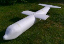
The story of a foam C130 Hercules build.
By Toni Reynaud
Part 1 – Building the basic airframe
One of the challenges I like to set myself in aeromodelling is to achieve the maximum fun for the minimum of outlay. I also like to try the occasional different type of model and construction techniques. Combine this with the enormous amount of information available on the internet, and vast possibilities open up. I had gone all electric when I came back into the sport about six years ago, and one of the good things about this is the ability to build multi-engined models. So, add foam and brown paper construction to multi-engines, a downloaded free plan for a simple build of a foam C130 Hercules (http://www.delago.de/ariane/EC130.htm), a big block of white foam thrown away from B&Q, and critical mass was achieved. The fact that in my last year in the RAF I was servicing Hercs at RAF Lyneham also influenced my choice of model.
I had cut foam wings with a hot wire before in the 70s and 80s, and I
still have the cutting bow I made then. My wife had rescued a variable
output lab power supply from the skip at the college where she worked,
so all the equipment was at hand.
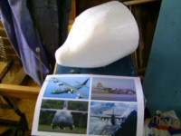
| The plan is an A4 sheet containing a top view of the Herc with all measurements marked on it, with two additional sheets showing the wing and fuselage sections, and the main page of the site contained very basic building instructions, so some original thought was also going to be required. Click to enlarge the image. |
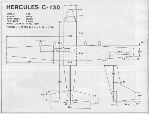
Just to check the plan,
I also downloaded a three-view
of a Hercules and superimposed
it on my working drawing.
I measured all the vital
dimensions, scaled them
up on a calculator and cross-checked
with the original plan and
created a big table of values,
and got a final set of working
measurements so close to
the original I need not
have bothered! I also downloaded
lots of photos just to get
really familiar with the
final shape.
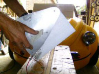
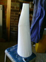
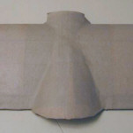
The first thing was to create templates from the plan for cutting the foam, which I made from 3mm (1/8 inch) ply rescued from the drawer bottoms from an old chest of drawers. I didn’t like the shape of the rear of the plane according to the plan – it was a single piece, completely circular and conical – so I modified that part of the plan to be a little more like the real thing, and from that created a couple of different templates to make a flattened double tailcone. I chamfered the edges of the templates and hardened them with CA – it turned out not quite enough, so next time I will reinforce the edges with copper wire CA’d on so that the hot wire slides easily along.
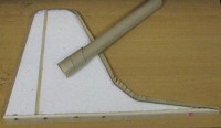
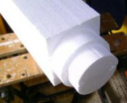
The foam block measured about 1,200 x 800 mm x 130mm thick (48 x 32 x 5 inches). The fuselage is 190mm (7½ inches) in diameter, so I cut the foam into basic blocks and glued it to form two bigger blocks about 240 x 190mm (9½ x 7½ inches) to get the fuselage bits from, then using the templates cut out the blocks for the nose, the fuselage centre tube and two tailcone parts.
For the nose, I made templates for the approximate top and side views and used these to cut a rough nose shape. A small hot wire cutter and very fine sandpaper was used to get to a final nose shape. These templates and the ones for the undercarriage sponsons were cut from an old piece of thin aluminium rescued when a gas fire had been removed from a previous house.
|
|
|
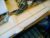
The top of the wing is level with the top of the fuselage, so I next cut out the aerofoil wing opening while the fuselage tube was still in the block, and cut the wing placement opening into the top of the fuselage to get the pieces to fair the top centre of the wing into place.
I also decided that I would add the undercarriage sponsons to the fuselage, more like the real thing, so I cut them from the fuselage block after removing the fuselage tube – this made sure that they would fit nicely in place. Next time I would also cut wing fairing fillets.
|
|
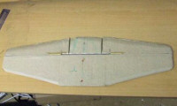
Because of the imperfection caused by the cutting wire snagging in a few places on the ply templates, I covered the wings in lightweight filler and sanded them smoother. I’m not a perfectionist by any means, but they looked a lot better for a couple of hours work. I had to do the same for the tailcones, too.
|
|
|
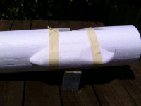
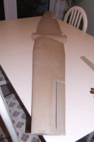
The wing sections were glued together using long-set epoxy (5-minute is suggested, but I had long-set in the workshop and plenty of time!) The tips were jigged with an offcut of the block from which they were cut to ensure that the top of the wing was flat and the washout was correct. The plan calls for 3mm (1/8 inch) square spars full width top and bottom, but I used a 10 x 3 mm (3/8 x 1/8 inch) piece of spruce that I had handy. I used a very small piece of hot wire to cut a 10 x 3 mm slot in the top of the wing and fitted the spar with more epoxy. The wing is 1,800mm (about 71 inches) long, and the spar is 1,000mm (39 inches) so the outer 400mm (15.75 inches) of each wing is not sparred, but the plan was to skin the foam with brown paper to add strength. I added a 30mm (1 inch) balsa trailing edge to prevent the paper from distorting the trailing edge as it dried and shrunk.
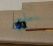
To cover with brown paper I used a 50/50 mix of PVA (left over from a building project!) and water, and some green food colouring to help show where it had been applied to the white foam. I coated the joined wing, fuselage and tail feathers with this and left it to dry. The paper was a £1 roll from a local cheap shop, and is very thin, much thinner than the best quality parcel paper you might buy in the Post Office. However, it’s quite tough and suits the purpose admirably.
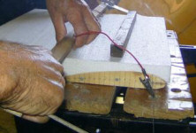
To cover the wings, I cut brown paper to the size and shape of the complete assembly for the bottom, and in two pieces for the top. I painted the PVA/Water mix onto the matt side of the paper, left it for a couple of minutes to ensure it soaked well in to get the paper flexible, then laid each piece in place and smoothed it down. The leading and trailing edges folded over easily enough, and for the tips and centre section of the top a few judiciously placed slits in the edges of the paper enabled me to get a smooth finish on the curves.
I used two small extra pieces on the awkwardly shaped centre section to help cover the compound curves. I left the wing to dry with the tip blocks in place and cans of beans holding the centre section down to prevent warping. When it was all dry I cut the ailerons out and papered over the exposed polystyrene edges, and cut holes for the servos, and for the servo and motor power wires. I ended up later cutting a separate slit for the servo wires, and once the servos were finally in place I papered over these slits.
|
|
|
I cut the tailplane and fin from 10mm (3/8 inch) flat sheet, and using a 50mm (2 inch) hot wire tapered the leading and trailing edges at about 45 degrees rather than have square edges. The elevators were cut off the tailplane and a 10 x 6 mm (½ x ¼ inch) balsa reinforcing spar fitted along the elevator hinge line and the front of the elevators. The elevator spar was tapered at about 30 degrees to allow for hinge movement. A joiner was formed from piano wire, and a groove cut into the top of the tailplane for this to run in, the elevators joined and hinged with glass reinforced packing tape, and finally the whole lot was papered in the same way as the wing.
The fin is also reinforced by a similar 10 x 6 mm reinforcing spar along the rudder line. A rudder is not used on this plane, so that was simply glued back in place. Because the fuselage is about 1600mm (63 inches) long, I decided that it couldn’t travel in the car with the tail feathers on, so I had to organise a way of making them detachable. To do this I fitted captive nuts into a 10 x 6 mm spar and glued it to the bottom of the fin, then with matching holes I screwed the tailplane to it. Another screw then comes up through the very rear of the fuselage through the tailplane into another captive nut in the base of the fin, and a fourth goes down through the front of the fin strake into a captive nut fitted on a ply plate inside the fuselage. The fin was then papered in the same way as the tailplane.
|
|