|
|||
|
|
|
||
| View Shopping Cart |
| Home |
| Guides Available |
| About the Author |
| FAQs |
| Testimonials |
| Articles |
| Contact Andrew |
| Terms & Conditions |
| Mailing List |
| Links |
 |
 |
Gibbs Guides.com
More high
quality information absolutely
free with every
Gibbs Guides newsletter.
Sign
up now!
Maximum
fun, minimum cost
The story of a foam C130 Hercules build.
By Toni Reynaud
Part 2 – Adding equipment and paint
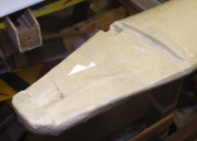
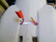
For mounting the motors, the basic instructions with the plans call for rolled cardboard tubes to be wrapped around the motors and fitted straight to the wing with glass-fibre reinforcement. I wanted a slightly more scale looking nacelles so I cut, carved and sanded some out of blue foam which was left over from the full-size Europa my son is building!
|
|
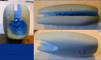
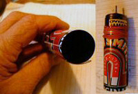
To carve the hole in the front of each nacelle I used a piece of beer can rubber-banded to a motor. I also cut a groove along the bottom to provide extra cooling and to accommodate the motor wires. I fitted the nacelles to the wing with hot glue.
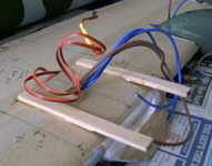
I extended the leads of the two aileron servos and soldered them together to make a permanent Y-lead, then fitted the servos and buried the wires in a new slot. This is just a knife cut in the lower surface of the wing, not a carved out channel like the one for the motor wires. I also connected the motor wires and fitted them into the previously prepared channel on the bottom of the wing with hot glue, then papered over all the grooves. The motor wires and those for the servos are spaced by 25mm (1 inch) to help ensure no interference is picked up by the RC wires.
I made the control surface
horns out of old credit
card type plastic and epoxied
them in place on both ailerons
and the elevator
|
|
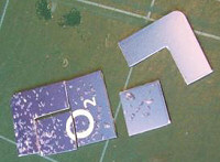
To fix the wings to the fuselage, I decided on a conventional arrangement of prongs going forward inside the fuselage from the bottom front of the wings, and a plate with captive nuts for hold down screws at the rear.
|
|
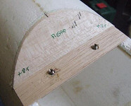
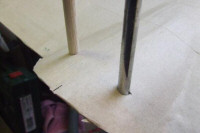
I used a section of old aerial tube to cut hole down through the rear of the wing assembly, then glued 10mm balsa dowel into the holes and drilled M3 holes down through these for the fixing screws. These holes were used to mark the positions of the captive nuts on the plate. I also used a piece of string to check that the tailplane fore and aft was lined up level with the lower surface of the wings (decalage!) as per instructions.
|
|
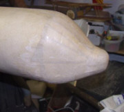
I covered the fuselage with smaller pieces of brown paper about 50-60 mm wide and 100-120 mm long. The final piece on the nose was a circle with lots of slits cut round the circumference to help getting it round the radome.
|
At the tail end, there is cut-out for the elevator servo under the leading edge of the tailplane. The servo is fitted with an extension lead down through a hole in the tailcone to reach the receiver. A control rod made from a large paper clip with an adjustable clevis soldered to it runs the short distance back to the elevator horn.
After this came the painting bit. I visited my local hardware shop, B&Q, looking at sample paint pots and got colours that are fairly close to the full size planes, and copied the camouflage pattern from various photos found on the net. The windows and portholes are just painted on, and a few panel lines for the doors and ramp are added with black and silver pens.
|
The motors consist of four Speed 400s, two Permax and two JP. I cut the power leads to be just longer than the nacelles and soldered them to the motors. The motors were then slid into the cutouts in the nacelles and several blobs of hot glue applied to the front edges and along the sides of the slots in the nacelle bottom. The motors were oriented so that one of the rear cooling slots was lined up with the bottom of the nacelle, and I had already removed foam at the inside of the top of the nacelle (with the trusty Dremel type tool from Aldi) to match up with the top cooling slot. All four motor are wired in parallel. I decided on the popular Günther 5” x 4.3” (125 x 110mm) props, which cost just £2.50 for four.
Now I had to do a little more detail work on the power system. The airframe with motors and 3 servos weighed 1,450g (3lb 3oz). Add a ten-cell 2,300mAh NiCd battery at 640g (1lb.6oz) as recommended in the plan (drawn about 1994) and the flying weight would leap to 2,100g (74 oz or 4lb 10oz). I also wanted to consider using LiPo batteries to keep the weight down, so some checking was in order. Accordingly I ran the motors up using a variety of batteries, and measured the results using a Medusa Power Analyser (similar to a Wattmeter):
| Hercules power system testing – 4 x 7.2V 400 motors | |||||
| Battery | Off Load | Current | Voltage | Watts | Comments |
| 10 x 2,400mAh NiCd cells | 13.4V | 39A | 8V | 330W | OK but heavy |
| 3,200 2S LiPo (from spares box) |
8.4V | 22A | 5.6V | 130W | Insufficient power - not useable |
| 2,500 3S LiPo (borrowed from Andrew) |
12.5V | 50A | 9.9V | 490W | 120 W/lb – plenty of power |
| 2,500 3S LiPo, throttled back to 22A | 12.5V | 22A | 11 V | 240W | 60 W/lb Cruising power |
Working on the basis of about 50W/lb being required to fly and with 120W/lb being available from a 10 cell NiCd pack (330W at full power), I felt the model should have enough power at a flying weight of 2,100g.
However, by using the 3S LiPo (weighing only 210g or 7oz) the flying weight dropped to 1,660g (3lb 10.5oz) and peak available power rose to nearly 500W, giving a whopping 136W/lb. Throttling back to 22A (of interest because the most efficient current for a Speed 400 is around 6A) produced about 240W which meant it should still fly well on part throttle.
|
Based on this analysis,
I decided that a 3S LiPo
pack was the way to go.
I finally chose to go with
two 3S 1500 20C LiPo batteries
in parallel so that I could
also use them singly in
other smaller models. Having
got them, I needed to find
a balance point. After using
two online CG Calculators
and much consideration,
I decided on a 25% chord
position to start with.
Both calculators came up
with 47 - 50%, but I thought
this position would probably
require loads of down elevator
to keep it level!
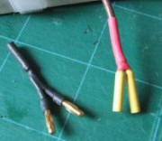
The next task was to sort
out a method of paralleling
the batteries to get an
effective 3,000mAh 3S LiPo,
and to get them into the
plane. I made up Y-lead
adapters for the batteries,
which was a relatively quick
and easy job.
|
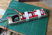
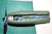
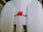
Next I needed to get the batteries into the model, so I made up a tray to hold them. This also holds the ESC so I named this the ‘power tray’. I added hook-and-loop straps right round the tray to hold them in, then hot glued more hook-and-loop into the bottom of the fuselage to hold it in place.
I marked the bottom of the wings with balance points between 25% and 45% and then balanced the model with the complete power tray on top of the plane to take measurements, then from those measurements marked up the inside of the plane to position the power tray.
As the wings are held on with two M3 screws, they are not removable quickly, so I needed to have a method of fitting the power tray into the plane, but only connecting power to the model after the wings were on. To do this I used a long positive battery lead and put a connector in the middle of it, long enough for the connection to be outside the fuselage. I made a couple of holes in the bottom of the fuselage by the handhold with a trough between them for the connected wire to hide in, so now I can fit the power tray, put the wings on, and then join the main power wire outside the plane and snug the connector away in its trough for flight.
|
|
|
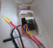
The ESC is from a car - it has no brake or auto cut-off, but is capable of 60 amps, well in excess of what I would be pulling. It lives in the power tray with the Y-leads and the long final connection leads.
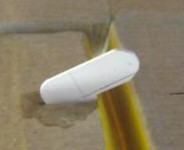
For ventilation, I used a sharpened 22mm pipe to drill a hole under the radome through to the inside of the fuselage, then disguised two of the rear portholes with chopped up