|
|||
|
|
|
||
| View Shopping Cart |
| Home |
| Guides Available |
| About the Author |
| FAQs |
| Testimonials |
| Articles |
| Contact Andrew |
| Terms & Conditions |
| Mailing List |
| Links |
 |
 |
Gibbs Guides.com
More high quality articles and information absolutely
free with every
Gibbs Guides newsletter. Sign up now!
Skyship
The story of a large RC flying saucer
Part 1 - Design and build
By John Gibbs
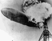
The well known tragedy of the Hindenburg’s fiery end at New Jersey’s Lakehurst Naval Air Station in 1937 left an enduring public perception that lighter than air travel was inherently unsafe. This wasn’t necessarily true, but the event effectively stopped the development of airships.
|
Nevertheless, interest in airships resurfaces from time to time, often with the idea of using helium as a lifting gas rather than flammable hydrogen. One such time was back in 1974, at which time I was teaching engineering at Portsmouth Polytechnic.
A colleague of mine named Robin Wren was involved with
a fledgling company whose purpose was to develop a viable modern airship.
One reason for this resurgence of interest was that airships had the potential
capability of transporting large loads to remote destinations where ground-based
transport or aircraft landing strips were not available. It was felt this
capability might be of interest to the military.
The design concept
The design concept which the Company had come up with centred on a lenticular
(saucer) shaped craft with a centrally mounted ducted fan. Unlike a conventionally
shaped airship, the lenticular form would generate a significant amount
of lift in forward flight. This would allow the craft to transport substantially
higher loads than could be achieved by pure lifting alone. To take off
at heavy weights the central lifting fan could be used, and where possible
a short take off run into wind could also be employed. The rear of the
craft featured a flat tail, which could provide pitch and roll control
when the airship was in forward flight.
Conventional airships are inherently difficult to control with precision near the ground, and the innovative design concept also addressed this issue. Propellers were to be mounted around the rim of the craft. These could be vectored, which allowed them to have several functions. When facing forward, they would be used to provide propulsive thrust for forward flight. Their thrust could also be used to control the craft in other ways. For example, they could be made to provide additional lift for take off and landing. When the craft was landed they could be vectored downwards to keep the machine ‘heavy’, or even sideways to counteract a side wind. Control in a rotational plane (yaw) could also be achieved.
This high degree of control also allowed the airship to be much less reliant on costly ground facilities such as the large masts and ground crew that traditional airships required in the past. So, all in all this was an attractive concept which the company was keen to explore.
Making the table model
Robin asked if I’d be willing get involved in the project by making
a table model of the Company’s new airship concept. The job was
too interesting to refuse so I agreed, even though I was already busy
with my job and my two small sons.
|
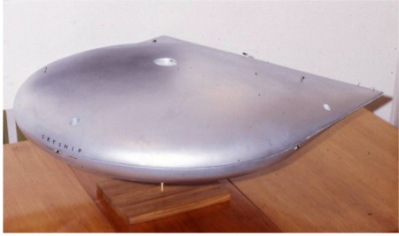
I decided to build the model from fibreglass. I’d worked with this material before while building plywood sailing dinghies, but this project would require the use of moulds. I used wood for this purpose. I needed to learn a bit about mould release agents, and after some experimentation I succeeded in producing a pair of shells, upper and lower. These were glued together to produce the basic shape, and some detail was added. The model was sprayed in silver paint and the name Skyship was added to the front. The finished result looked very handsome and I was rather proud of the model.
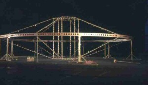
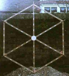
The complete airship skeleton.
In principle, the construction was very much like a bicycle wheel,
with a ring beam (rim) linked to a pair of centre frames (making
a hub) by a number of spokes. Every component was designed to be
as light as possible. The support props were there to aid assembly. |
A larger model
The company then decided to commission a 10 metre (30 feet) diameter,
proof-of-concept flying model to help evaluate the flying characteristics
of this unusual shape. I was very pleased to be offered the contract to
build the primary structure of this model, which was to be helium filled
and radio controlled. With a wife, two children, a mortgage and a cat
to fund, a little extra cash would be welcome. Robin, who was also an
engineer, did the design work and so we were able to work closely together.
I became intrigued by the necessary calculations needed to determine the
relationship between the required volume of lifting gas and the overall
weight of the craft. It became increasingly apparent that the model’s
structure would need to be exceedingly light in weight. We had some interesting
discussions as to how this could be achieved.
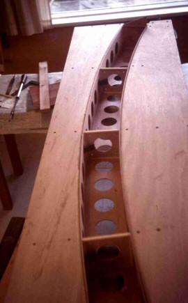
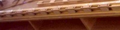
A ring beam segment under
construction in the large two-part jig. Altogether, twelve segments
were made which were bolted together to form the complete 10 m diameter
ring. |
Ring beam
The ring beam was to be made in twelve equal segments. Each segment was
made as a curved, 100mm (4 inch) square box section, fabricated from lightweight
3mm (1/8 inch) plywood. A flange was included at each end to enable each
segment to be bolted to its neighbour. Special lightweight bolts were
used for this.
To enable the fabrication of the ring beam segments, a large jig was first made from 18mm (3/4 inch) ply. This enabled the two vertical faces of each segment to be held accurately in place while the rest of the construction proceeded. A number of square formers were then positioned at intervals between the vertical faces to provide the segment with sufficient rigidity.
In order to reduce weight numerous large holes were made in every face of the segments. My younger son Iain entered into the spirit of the thing by sanding each and every hole with sandpaper wrapped around a plastic bottle. Andrew was probably too busy designing and building model aircraft to join in! Finally the upper and lower surfaces of the ring beam were glued in place using Cascamite. These were held in place while the glue set using lots of elastic bands positioned through the holes as shown in the photograph below:
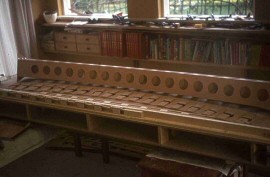
Multiple elastic bands and
temporary spreader plates were used to glue and clamp the top and
bottom faces of the ring beam. |
Spokes
Each “spoke” consisted of four 6mm (1/4 inch) square ramin
(wood) strips which were held apart by 25mm (1 inch) balsa blocks. Each
spoke was assembled and glued up using a flat board and by clamping each
block down with small plates and screws.
Close up of a balsa and ramin
spoke. |
Centre frames
The centre frames were constructed from ramin (wood) strips and balsa
blocks, in a similar way to the spokes.
One of the two centre frames. |
While I’d been busy constructing the frame, my colleague had undertaken many of the remaining aspects of the job such as making the craft’s outer covering and organising the power and control systems.