|
|||
|
|
|
||
| View Shopping Cart |
| Home |
| Guides Available |
| About the Author |
| FAQs |
| Testimonials |
| Articles |
| Contact Andrew |
| Terms & Conditions |
| Mailing List |
| Links |
 |
 |
Get more high quality
articles like this one, absolutely free
with every Gibbs Guides e-magazine. Click
here!
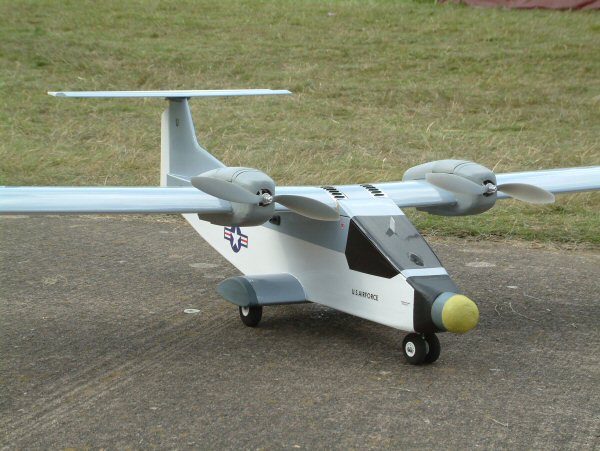
Mike White's Isn't This A Lovely Day
Article by Mike White

Introduction by Andrew Gibbs
This large tailless electric powered glider makes a refreshingly
different, striking sight. The designer Mike White, is
also responsible for the Quo Vadis design, described elsewhere
on this site. Mike takes up his story of this attractive
unusually shaped, and unusually named model.
Introduction
'Isn`t This a Lovely Day' may be an unusual name for a
glider, but that's what it was on the day
of the maiden flight. Somehow this became the model's
name!
Inspiration
for the model
I had a spare wing available which I wanted to use. I
have built tailless models before, and I thought that
another really large tailless model would make a good
project.
Construction
The fuselage is constructed using 2mm lite ply
sides with top and bottom from 3/8 sheet balsa. The wing
has a foam core, which I cut using a hot wire cutter.
I chose the Eppler 180 aerofoil section, but the aerofoil
was cut with the root rib set at right-angles to the trailing
edge, as this was the only way it would fit in the cutting
machine. This means the section is fractionally
different from a true E180 section. Anyway, the model
seems to fly well! The wing has about 1 degree of washout.
As well as this, there is about 1/8th inch of reflex added
to the elevons.
Each lower wing surface has a 40 inch, 6mm diameter carbon fibre tube epoxied into it. There is no balsa or obechi skin; instead 0.6 ounce glass cloth was applied directly to the foam using Poly-C varnish. The tip fins are 2 laminations of 6mm Depron. This material was chosen to keep the weight at the tips to a minimum.
|
|


Control
and RC
Control of the model is by rudder and elevon, as well
as trailing edge air brake flaps. Five servos are used
in total.
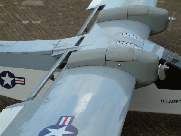
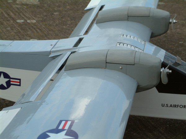
Trailing
edge airbrake flaps
The inner part of the trailing edge incorporates an airbrake
flap which consists of a short moveable surface which
can be extended upwards to about 85 degrees, and down
to around 5 degrees.
Power System
The power system comprises a Thumper 3536/910 (910Kv)
outrunner turning a Cam Aeronaut 12 x 6.5 folding propeller.
This combination draws 27 amps from a 2S 3,000mAh lipo,
equating to about 200 watts of power. The wing span is
95 inches and the model has a wing area of 10 sq .ft.
area. The flying weight is 80 ounces (5 pounds) which
means the wing loading is 8 oz / sq ft and the power loading
is 40 watts per pound.
This power system gives four climbs to 800 feet which is set on the Winged Shadow altitude limiter (see below). With the 2,500mAh receiver battery total flight time is long enough to give 4 flights in excess of 20 minutes each in still air conditions.
| The insides of the model. Space is at a premium. | The insides of the model. There's not a lot of room in here. |


Flying
The very low wing loading, just 8 oz/sq ft, and the abundance
of power means that launching is easy, there being no
'sag' after launch. All that's required to get the machine
safely away is to give a very positive forward push.
Airbrake flap operation
At small angles of deflection the airbrake flaps have
the effect of applying some up elevon. In this condition
there is little drag increase. When deflected upwards,
the airbrake flaps cause a nose up pitch. To counteract
this I set up a transmitter mix, so that as the airbrake
flaps are extended, down elevon is applied. Establishing
the correct mix requires some experimentation, as no two
models are exactly the same. Also the balance point does
make a difference to the nose down trim required.
At high angles of deflection the airbrake flaps produce a significant increase in drag. In the landing approach, the airbrake is progressively but not too quickly applied. With the down elevon transmitter mix I have set (elevons about a quarter inch down) she settles into a nose down pitch attitude with very little speed increase.
I am experimenting by setting the airbrake flaps about 1/8 inch down for the launch to locally increase the camber of the wing. In this condition I hope that the climb rate will be higher with a little less power set. This setting stays for the cruise while looking for thermals.
| Lovely Day passes close by designer Mike White for the camera. | The airbrake flaps are located at the trailing edge of the wing next to the elevons. |


Altitude
Limiter
The altitude limiter is an electronic gizmo which senses
a pre-set altitude and shuts the motor down when this
is reached. It may be used again when the altitude is
reduced. I like gadgets!!! Used with the electronic recording
altimeter fitted it makes for interesting flight testing
and general flying.
Thermal
detector
I also fitted a Winged Shadow thermal detector. When lift
is detected the rudder moves from side to side. This is
switched out at the transmitter for the climb, and switched
on for the cruise. I did have a few sweaty moments
during the first use as I had forgotten to switch the
detector out. As you can imagine the climb and ensuing,
almost uncontrollable antics, were a scream but nevertheless
very worrying, until I remembered to switch the thing
off.
| The airbrake flaps in the raised position. | The model flies well, but rudder response is poor, perhaps due to the short moment arm. |


Conclusion
and thanks
The project was successful and I am happy with the way
the model flies. The air brakes may be even more effective
if they were larger but as they are, they seem to work
fine when the elevon pitch mode is mixed to compensate
the nose up trim change. I would have liked to have the
servo wire leads easier to connect when attaching the
wings. At the moment they are a bit messy and the room
inside the fuse is at a premium.
Thanks to my flying buddy Peter Lloyd-Davis for being
the launch master and for taking the flying shots.
| Lovely Day technical data | ||
| Span | 2,413 mm | 95 inches |
| Root/tip chord | 570/292 mm | 22.5/11.5 inches |
| Wing Area |
0.00 sq m | 10.0 sq ft (1,440 sq in) |
| Flying Weight | 2,268g | 5lb (80oz) |
| Wing Loading | 00g/dm | 8 oz/sq ft |
| Battery | 2S 3,000 mAh LiPo | |
| Motors | Thumper 3536-910 (Kv 910) | |
| Prop | CAM 12x6.5 folder approx 00,000 rpm | |
| Max Power | 27A / 200 Watts | |
| Power Loading | 000 W/kg | Approx 40 W/lb |
| Endurance | Approx 80min | |
| Control functions | Elevons, airbrake-flaps, rudder & throttle. 2,500mAh 4-cell NiMH receiver battery | |
Get more articles like
this one absolutely free with every
Gibbs Guides e-magazine. Join
the mailing list!