|
|||
|
|
|
||
| View Shopping Cart |
| Home |
| Guides Available |
| About the Author |
| FAQs |
| Testimonials |
| Articles |
| Contact Andrew |
| Terms & Conditions |
| Mailing List |
| Links |
 |
 |
Get more articles like
this one absolutely free with every
Gibbs Guides e-magazine. Join
the mailing list!
How to Avoid Crashing
Part 3 - Building for Survival: The Control System
Article by Andrew Gibbs
The Control System
A properly set up control system is a most important part
of ensuring a model’s long term success and survival.
Setting up control systems seems to be a forgotten art,
and is an area in which many models will benefit from
care, attention, and perhaps also some improvements. Setting
up the controls of a new model properly requires a significant
investment of time and a willingness to give attention
to detail. It really doesn't pay to try and rush this
process. Take your time, and get each control working
perfectly.
Mounting servos
For each control function, check first that the servo
is securely mounted so that it is not able to wobble about.
For servos mounted using rubber grommets and eyelets,
make sure these components are correctly assembled - the
eyelet should be inserted from beneath i.e. the eyelet's
widest part should be between the servo and the mounting
surface.
Hardware quality
The control system hardware supplied with a model is usually
adequate for the job, but occasionally poor quality hardware
is found. If necessary, be willing to replace items such
as clevises and control horns – considering the
relatively low cost of these items, its not worth risking
the safety of the entire model.
Minimise slop
The control linkages generally consist of one of three
basic designs; snakes, pushrods or a closed loop system.
There isn’t space here to discuss the pros and cons
of each, but whichever system you choose, it should be
assembled taking particular care to minimise any slop,
or free play.
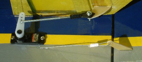
You may need to drill out the holes in a servo arm to accommodate the pin of a clevis. In this case, make sure the new hole is no larger than necessary, otherwise there will be undesirable play or slop in the control. The same applies at the control arm for the surface in question. I like to have a set of drills available which increase in size in very small increments - these are ideal for ensuring holes are no larger than necessary.
|
|


Control Throws
The instructions should specify the amount of control
surface movement necessary. Some modelers increase these
throws, reasoning that more control is better than less.
However, in my view this is a mistake. Increased throws
may well mean an over-sensitive model which is twitchy
and difficult to control accurately, especially when landing.
I have been reading model reviews for many decades, and
I do not ever recall hearing about a model that crashed
due to insufficient control authority. However, many,
many models have been crashed due to having too much control
movement!
Wiring
RC system wiring should be arranged so that it is as far
away as possible from the wiring of the electric power
system. It's also worth making sure wires from servos,
UBEC units and so on are not loose and able to move around
in flight, because eventually loose wires can break.
| Excessive control surface movement makes models more difficult to fly accurately and harder to land with precision. | Wires from ESCs etc must not be allowed to flop about. This UBEC wire is safely secured at both ends. |


Total servo movement
The maximum amount servo movement i.e. the amount of angular
rotation can be adjusted from the usual 100% at the transmitter.
For example, my JR transmitter allows me to set anything
from 0% up to 150% of normal servo movement.
For controls which have too much movement it can be very tempting to reduce the overall servo throw using this function of the transmitter. However, there are two disadvantages to doing this:
1. Servo power is effectively reduced when the total servo movement (termed travel volume by Futaba) is reduced. Also, for a given control input, the servo has to work harder.
2. As the total servo throw is decreased, the proportion of play, or slop, in the control system is effectively increased.
If the amount of control throw needs to be reduced, it is better by far to accomplish this by adjusting the physical geometry of the model’s control system. If a control has too much movement, reposition the linkage so that it attaches to the control arm of the control surface a hole further from the surface itself. The same servo movement will now translate to a smaller control surface movement.
Alternatively (or even as well), you can reposition the control linkage to connect to the servo's output arm using a hole nearer to the centre of the servo. This will provide less overall travel for the surface.
Applying this practice reduces control surface slop and maintains effective servo power. Ideally, the travel volume function should only be used to make small adjustments that cannot be made by using different holes on the servo arm of control horn.
Avoid binding/jamming
Make sure that with the transmitter stick at full deflection,
the linkage is not binding on the servo. A buzzing servo
is a give away that this is happening.
| The amount of control throw should be as much as is required, but no more. A common beginner mistake is setting controls up with too much travel. | Differential throw is often a great idea for ailerons. A 2:1 ratio (more up than down) is a good starting point. |


Elevators
It is usual to set elevators up with the same amount of
up and down movement. Make sure the total movement is
not excessive, as this can make an accurate landing flare
difficult to execute. Adding some exponential (explanation
below) may be useful to desensitise the control response
around neutral, which may help with landing.
Rudder
Plenty of rudder movement is often necessary to allow
sufficient control authority both for taxiing and also
for stall turns. However, the control must not be so sensitive
that smooth, straight take offs become difficult. The
addition of expo can be of particular assistance for the
rudder control in this regard.
| The clevises on this model have yet to have keepers added. | All hardware must be fit for purpose. Replace any items which are not of good quality. |


Ailerons
When any control is deflected, it will generate drag.
This is of particular importance for the ailerons because
the down going aileron is a particularly prone to generating
drag, and this can cause a phenomena known as adverse
yaw. For example, suppose we want to roll the model to
the right. A right aileron command will mean the left
aileron is lowered and the right one is raised. Because
the left hand aileron is going down, it will generate
more drag. If the left hand (down-going) aileron produces
a large increase in drag compared to the up-going one,
an airplane could have a tendency to yaw (nose swinging
to one side) to the left - this is the opposite direction
to the intended direction of turn.
Often, an effective solution for this is to adjust the aileron travel so that the down going aileron has a significantly reduced travel compared to the up going one. This is known as differential aileron and it works because the additional drag caused by the down-going aileron is reduced.
Adverse yaw affects full size aircraft as well, and differential aileron is more likely to be necessary for models (and full size airplanes) with high aspect ratio wings, such as gliders and certain light aircraft like the Piper Cub. Setting up ailerons in this way carries an additional bonus in that tip stalling becomes less likely in low speed situations such as take off and approach, making for safer flying. I almost always set my own models up with differential aileron travel. A ratio of 2:1 is a good starting point. To maintain servo power, it's best to arrange for differential aileron to be provided geometrically rather than by electronically limiting travel in one direction.
It’s worth noting that for good quality balanced turns, all aircraft including models need a combination of aileron and rudder. Generally, the higher the aspect ratio the greater the proportion of rudder that is required.
Many full size aircraft are designed with differential aileron movement, so the value of this is well established. For example, the Tiger Moth has much less down-going aileron than up.
Differential movement reduces the likelihood of a model suffering from tip stalling during flight, especially on take-off when airspeed is low. The only disadvantage to setting up ailerons with differential movement is that the risk of tip stalling is increased during inverted flight. However, the model is very unlikely to be traveling slowly enough while inverted for this to be a problem. As long as inverted flight is not carried out slowly or with large amounts of aileron movement, there should be no adverse effects. In any case, the amount of differential aileron should not be any more than is needed.
One final point on ailerons - if you have a model with more down aileron than up, this is likely to pose a serious risk to your model's health. This condition should definitely be corrected before trying to fly the model.
|
Exponential can be used
to soften or desensitise the model's control response
around the neutral point. |
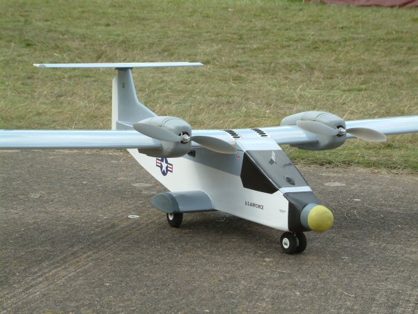
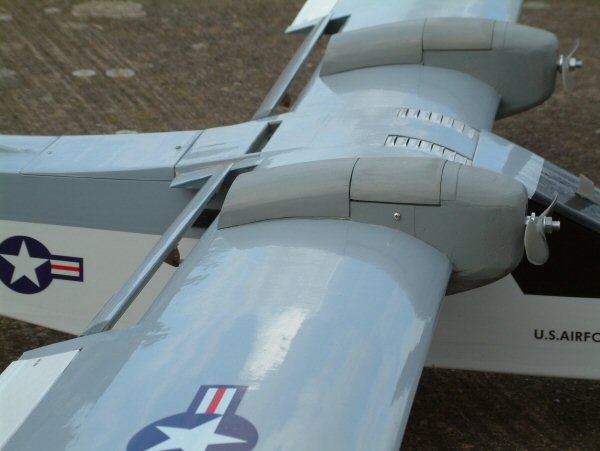
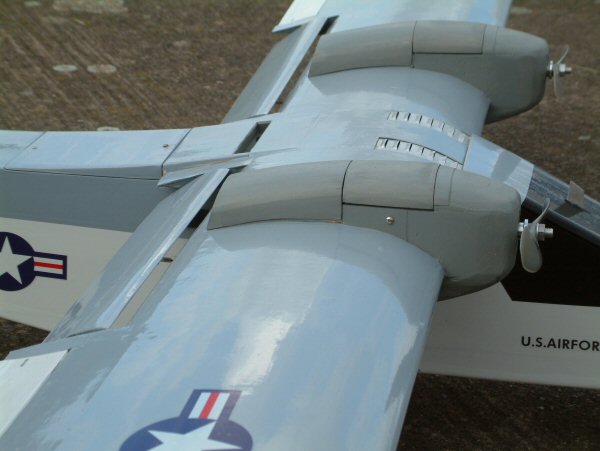
Check your model carefully - it's easy to miss a small detail. Can you see the missing parts? |


Exponential (expo)
Modern computer radios have many features which make radio
set up much easier than it used to be. Exponential, or
expo for short, is a particularly useful function, and
this is usually used to soften or desensitise or soften
a control around the neutral point. I usually start with
around 25% expo on all surfaces.
Note that expo can be set positive (+ve) or negative (–ve), and if this variable is set up in the incorrect sense, the control will become more sensitive around the neutral point, not less, making the model much harder to fly accurately.
Checking the sense of expo
The expo setting to produce a softer neutral is termed
+ve by some manufacturers (e.g. JR) and –ve by others
(e.g. Futaba). To check the sense of the expo I have set
up, I like to temporarily ramp it up to a very high value
e.g. +95 % as a check. If the control then becomes very
insensitive around the neutral point, this confirms that
+ is the correct sense for a softer neutral. The expo
is then returned back to a sensible value, perhaps +25%.
However if the control became very sensitive around the neutral point and less so as the stick was moved further away from neutral, this would tell me that +ve expo was incorrect and I would know to select –ve expo for softer neutrals. I would repeat the test going all the way to -95% to confirm my conclusion. I would then assign a suitable –ve value of expo.
Balance/harmonisation
It's worth spending a little time test flying a model
and making adjustments to the controls so that the response
of the elevator and aileron controls feel similar. A model
will be unpleasant to fly if for example the elevator
is much more sensitive than the ailerons.
Get more articles like
this one absolutely free with every
Gibbs Guides e-magazine. Join
the mailing list!