|
|||
|
|
|
||
| View Shopping Cart |
| Home |
| Guides Available |
| About the Author |
| FAQs |
| Testimonials |
| Articles |
| Contact Andrew |
| Terms & Conditions |
| Mailing List |
| Links |
 |
 |
Gibbs Guides.com
More high
quality information absolutely
free with every
Gibbs Guides newsletter.
Sign
up now!
How to add a separate power supply for a retract servo
By Andrew Gibbs
Chris wrote to me about his large P51 Mustang model, asking:
Hi Andrew, I’m just finishing the assembly of 65 inch span ARTF P51 Mustang which has a set of mechanical (servo operated) retracts fitted. In the past I’ve had gear legs get stuck. My concern again now is that if the retracts stick in flight the receiver battery might go flat, resulting in a loss of control. A club mate suggested that I simply increase the capacity of my receiver battery but I have heard it is possible to power the retract servo using a separate battery. Can you tell me how to do this please, and give details of wiring and battery size?
Thanks for your question, Chris. Its really simple to arrange for a seperate battery to supply the retracts and this article will describe how to do this.
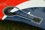
As you are aware, any retract mechanism such as that shown in the photo below can become bent during take off or landing, especially if operating from an uneven runway surface.
|
Any distortion of the undercarriage (gear) legs can prevent them from fully retracting. This can easily cause the retract servo to become stalled, as you mention. A stalled servo will draw a high current. This can flatten a battery very quickly which will of course result in a complete loss of control if the battery also supplies the receiver.
A high capacity receiver battery will only allow more time before a loss of control occurs so this is only a partial answer to this problem. A much better solution is to provide a separate battery to power the retract servo alone. This means that the receiver and flight control servos will be unaffected by any problems occurring with the servo operated retract system.
I’ve drawn out the diagram below to show how this can be achieved simply and without requiring any soldering work. The components that you will require for this easy modification are:
i) An additional suitable
battery to power the retract
servo
ii) An additional switch
harness
iii) A ‘Y’ lead,
which will be slightly modified
Please click image for a larger version Note that in fact only two wires will be connected through the switch harness, not the three as shown. |
Servos are connected using three wires – two of them, the red (positive) and black (negative) supply the servo with electrical power, while the third wire sends the control signal from the receiver to the servo. To provide a servo with its own, independent supply of power all we need to do is cut the positive supply wire, and then arrange to provide the servo with a separate positive supply from another battery. By this means, the servo is still controlled by the receiver, but draws its power from a separate battery – exactly what’s required.
Referring to the diagram, we can see that the receiver battery (not shown) is prevented from supplying the retract servo with power because the Y-lead lead has had a short length of its red (positive) wire removed at the receiver end. The retract servo will therefore draw its power from the seperate retract battery. Note that the positive connection between the other two ends of the ‘Y’ lead is preserved, and this connection allows the separate battery to supply the retract servo. The receiver maintains control over the retract servo in the normal way, via the intact black (negative) and the yellow/orange/white (signal) leads.
Make sure you remove a short length of wire - don’t just cut it as this still leaves the possibility for the two cut ends to touch each other which could cause problems. If you’d rather not permanently alter a Y-lead, another possibility is to carefully ease out the relevant pin of the Y-lead connector housing. Alternatively you can add a short extension lead between the receiver and the ‘Y’ lead, and make the break in the positive wire of that lead instead. Be sure to mark the modified lead in some way that will remind you it’s been altered, otherwise you might later find its ‘faulty’!.
I don’t know what make your RC gear is, so I’ve included below a table covering Futaba, JR and Hitec equipment.
| Futaba | Hitec | JR | |
| Positive | Red | Red | Red |
| Negative | Black | Black | Brown |
| Signal | White | Yellow | Orange |
You’ll need to fit a second switch harness for the retract battery, and of course make sure that you charge both on-board batteries before flying. The retract battery only needs to store enough energy to operate the gear a few times during a flying session, so there’s no pressing need to fit a high capacity battery. However, you don’t want a battery that’s so small that its own internal resistance will cause an unhealthy reduction in servo

Happy landings! Look carefully,
and you can see that all is not well with this P51’s starboard
gear leg. However, with a separate retract power supply, even if
the servo remains stalled for the entire flight the supply to the
receiver and flight control servos will not be affected, allowing
confidence that control will be maintained. A flat retract battery
should therefore result in nothing worse than a gear up belly landing. |
operating power either. I’d probably start off using a spare receiver battery of around 600mAh but if your model can comfortably afford the weight there’s no harm in using a larger one. An alternative would be to use a LiPo battery and a suitable regulator or UBEC which will provide a very light weight set up. A two-cell LiPo is most usual in this case, but some regulators will work with three of more cells.
Once you’ve finished the wiring work, remember to check your work carefully. I always recommend a range check any time a model’s installation has been altered, because any wiring or installation changes can degrade a receiver’s performance. This precaution applies whichever type of rc equipment is fitted.
Finally, you may like to consider setting up your transmitter so that the gear is down when the switch is physically in the ‘down’ position. This emulates full size practice, and I find it makes it much easier to remember which switch position corresponds with the required gear position.
If you find it difficult to remember which switch operates the gear, then adding a coloured sleeve can be a useful memory aid. You may agree that a black or grey sleeve would be the most appropriate, as this colour corresponds to that of the tyres.