|
|||
|
|
|
||
| View Shopping Cart |
| Home |
| Guides Available |
| About the Author |
| FAQs |
| Testimonials |
| Articles |
| Contact Andrew |
| Terms & Conditions |
| Mailing List |
| Links |
 |
 |
Gibbs Guides.com
More high
quality information absolutely
free with every
Gibbs Guides newsletter.
Sign
up now!
Propeller problems!
By Andrew Gibbs

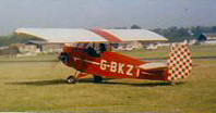
No
photograph survives
of the Magicfly I
built, but I did find
this 1978 advert for
the kit. The design
utilised a really
thick (14.5%), flat
bottomed wing section
with strip ailerons
and tip plates. The
model was available
in foam and built-up
balsa wing variants. |
The first electric RC model I ever built was the Magicfly, by Model Flight Accessories (MFA). This was in the really early days of electric powered RC flight, around 1979, while I still a schoolboy. A discussion of the difficulties I experienced still has some relevance to today’s electric models.
This 48 inch span foam winged model was powered by a geared 540 motor (a sort of early 600 motor), 8 x 1200mAh NiCad cells, a 12x4 Kiel Kraft plastic prop of dubious efficiency and nothing more sophisticated for motor control than a servo-operated on/off microswitch. The model was successful in that it did fly, but was disappointingly lacking in performance, usually having only just enough thrust to be capable of flight. I remember that it was more or less a ‘one speed’ model; unless it was flown at precisely the correct airspeed, (set by the elevator) it simply would notclimb. This experience proved to be useful many years later when I flew a full sized FRED homebuilt, powered by an old VW Beetle engine, which had a similar, alarmingly poor rate of climb!
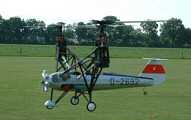
Taxiing
out for my one and
only flight in this
underpowered F.R.E.D. |
Returning to the Magicfly, I don’t remember how long the motor would run for, but this was irrelevant because I was forced to land well before the batteries were exhausted simply because the model could only sustain flight with well charged batteries!

Fairoaks
airport, 1993. Being
briefed by the owner
of the F.R.E.D. The
initials stand for
Flying Runabout Experimental
Design, the aircraft
was designed by Eric
Clutton, an aeromodeller
of some repute, now
living in the USA.
The wing’s pronounced
undercamber can be
seen very clearly. |
At that time electric modeling really was a ‘black art’, with very little information around to help the newcomer. Although there was the odd magazine article, I never found that these answered my many questions. I think it was the troubles I experienced with this model fuelled a desire to thoroughly understand and explain the technicalities of electric flight, a passion which lasts to this day.
Many years later on, it’s now clear to me why this model was lacking in performance. For success with an electric power model, especially when using brushed motors such as the old 540 the Magicfly used, there needs to be enough power, plus each element of the entire power system needs to operate at a reasonable level of efficiency to ensure the available power is not unnecessarily wasted. Thus the motor, propeller and battery all need to be considered. Let’s look at each of these factors in turn:
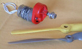
An
old 540 motor and
gearbox, similar to
the unit installed
in the Magicfly. The
yellow prop is a Keil
Kraft 12 x 4. Alongside
it is a modern electric
prop. |
Available
Power
The Magicfly weighed around
3lbs (1,360g), and I estimate
that its 540 motor would
have consumed around 15Amps.
Today, it’s generally
accepted that 50 Watts per
pound is sufficient for
this type of model, though
it’s fair to say that
some 25 years ago our performance
expectations were lower,
so 40 watts per pound would
probably have been considered
just about enough.
A motor drawing 15A at 8V (the likely on-load voltage for an early 8 cell pack of nicads) has an input power of 120 watts. (15x8 = 120) This indeed equates to 40 watts per pound, and so the model probably did have sufficient power - its problem was therefore more likely to do with how efficiently that power was used.
Propeller
I remember that judging
by the way the model pulled
at full throttle, the Magicfly
seemed to have an impressive
static thrust (the thrust
at zero airspeed), and I
was mystified as to why
it had so little airborne
performance. Interestingly,
looking through some old
back issues, I read that
an RCM&E reviewer also
found the model was a somewhat
marginal performer, so I
was not alone. However,
he at least was using the
recommended prop!
In fact, I had not understood the importance of the propeller factors that need to be considered with electric power models. Perhaps the three most important of these are pitch speed and dynamic thrust (the thrust at flying speed) and pitch to diameter ratio. (These themes are explored in more detail in the article ‘A few words about propellers’ – add this sentence when the prop article is added)
Static
& dynamic thrust
Static thrust is often measured
by modelers; it’s
an easy measurement to make,
requiring little more than
a simple spring balance,
and seems at first sight
to be a useful indicator
of flying performance. However,
static thrust is only really
of relevance at zero airspeed;
the only such situations
I can think of are
a) At the first instant
of take off
b) During prop hanging maneuvers
c) The rotor of a helicopter
in hovering flight
|
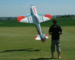 |
| It is static thrust keeping these models airborne. The extraordinary scale FW61 helicopter was designed and built by the remarkably skilled Dutch modeller Appie Van Moorst, and was seen at an electric meet in Holland in 2004. The equally extraordinary large prop hanging electric model has 12 kilowatts of power on tap. Ian Watson of FlightTech is the talented pilot. | |
All of these are zero airspeed situations. However, as soon as a model is moving, it is dynamic thrust that counts. Unfortunately, for the average modeller without access to specialized equipment such as a wind tunnel, dynamic thrust is impossible to measure.
So what can we do? Well, the usual method is to avoid tackling the question of dynamic thrust head-on. Instead, we simply ensure that sufficient power is installed in the model and trust that with a suitable propeller installed that the resulting dynamic thrust will be sufficient.
One of the factors by which we can assess whether of not a prop is suitable is its pitch speed. For the average model, this method tends to work very well. After this, it’s a matter of experimenting with different props to find the best match for the particular combination of motor, model and the required flying style.
Pitch
speed
Propeller pitch is defined
as the distance that a prop
will try to move forward
in one revolution - for
example, a prop with a 6
inch pitch will try to move
forward 6 inches with each
revolution. To help visualize
this, we can liken the prop
to a screw thread, which,
with each turn, tries to
pull itself forward as it
is rotated.
If we also know the rotational speed of the prop, then we can say with some confidence what the forward speed of the propeller will try to be – this is known as the pitch speed. It can be seen that pitch speed is affected by only two factors: pitch and rpm.
Pitch speed is therefore defined as the speed at which a propeller will try to move forward as it rotates, if no resistance to its forward motion exists. In practice, some resistance will exist, and is caused by the aerodynamic drag of a model. This drag will cause some ‘slippage’, so the actual distance the model will move forward with each revolution of the prop will normally be less than the pitch speed. If it helps getting to grips with the idea, pitch speed can also be thought of as the speed at which air will be ‘thrown back’ by the prop.
The table below shows the pitch speed resulting from various combinations of prop rpm and prop pitch. For example, it shows that a prop with a pitch of 8 inches rotating at 5,000rpm will give a pitch speed of about 38mph.
Pitch
speed of various props
at selected rpm. |
||||
| Prop pitch | 4000rpm | 5000rpm | 6000rpm | 7000rpm |
| 4 inches | 15mph | 19mph | 23mph | 27mph |
| 5 inches | 19mph | 24mph | 28mph | 33mph |
| 6 inches | 23mph | 28mph | 34mph | 40mph |
| 7 inches | 27mph | 33mph | 40mph | 46mph |
| 8 inches | 30mph | 38mph | 45mph | 53mph |
Although the figures in the table have been carefully calculated, notice that a fair approximation of pitch speed can be made simply by multiplying prop pitch in inches by rpm in thousands – for example 8 inches x 5,000rpm = approximately 8 x 5 = 40 mph. This is very close to the table speed of 38mph, and quite accurate enough for most purposes.
A poor
choice of prop
From memory, I recall that
the plan called for an 11x6
prop. Knowing very little
about such matters, I had
instead fitted the model
with an old plastic 12x4
from my spares box, which
was meant for internal combustion
(i.c.) models. I used it
simply because modeling
funds were tight and to
my inexperienced eye it
looked close enough in size.
At that time, I didn’t
really understand about
propeller pitch so I didn’t
give this issue much thought.
However, it’s now
clear that this prop was
a bad choice because the
4 inches of pitch was far
too low, resulting in too
low a pitch speed.
Being meant for an i.c. model, this sturdy nylon prop was also relatively heavy. Furthermore, the blade shape of this i.c. prop was probably rather inefficient for the low rotational speeds offered by the geared ferrite electric motor. However, in those days suitable lightweight electric props were simply not available.
Choice
of pitch
Let’s now look at
the pitch speed issue in
more detail. The 540 motor
I used probably achieved
about 15,000rpm on its freshly
charged 8-cell pack. The
gearbox used had a 3:1 ratio,
so this meant that the prop
speed was probably around
5,000 rpm, giving a pitch
speed of about 19 mph (from
the table). Since some slippage
is inevitable, the maximum
possible flying speed would
have been at best a few
mph less, perhaps 16mph,
a slow speed indeed.
This slow pitch speed almost certainly corresponded closely to the minimum possible flying speed of the model. Additionally, it was probably also close to the minimum drag speed of the model. The propeller provided just enough dynamic thrust to keep it airborne at this one speed. This explains why the model had been a ‘one speed’ device – if it was flown at a higher or lower speed than this, drag exceeded thrust and it descended. Tricky indeed!
Pitch
to diameter ratio
All else being equal (which
is rarely the case in aeromodelling)
props with low pitch to
diameter ratios are considered
to be inefficient, and that
generally, those with a
ratio of less than 0.5 are
best avoided. That old 12x4
was down around 0.33 (4/12
= p/d ratio 0.33) so its
efficiency was probably
very poor.
I did try a number of other props without success, but due to ignorance of the cause of the problem, these did not include an 11x6 or 12x6 – had I done so, things might have worked out a lot better on all counts - the pitch speed would have been closer to about 30mph, the pitch/diameter ratio would have been more efficient at about 0.5 (6/12 = p/d ratio 0.5) and also I’d have had more power from the motor due to the higher load. Unfortunately I hadn’t realized that I was so close to success, and so I sold the model on. I hope its new owner had a better selection of props than I did!