|
|||
|
|
|
||
| View Shopping Cart |
| Home |
| Guides Available |
| About the Author |
| FAQs |
| Testimonials |
| Articles |
| Contact Andrew |
| Terms & Conditions |
| Mailing List |
| Links |
 |
 |
Gibbs Guides.com
More high
quality information absolutely
free with every
Gibbs Guides newsletter.
Sign
up now!
Charger cable project
By Andrew Gibbs
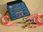
Most of the 12V power supply cables fitted to my chargers approach 2 meters in length as supplied. This length is necessary so that when the charger is powered from a vehicle battery it can be placed safely on the ground, well away from the vehicle’s engine bay. However, I’ve often found such a generous length of cable rather inconvenient in a workshop environment, especially when a mains powered 12V supply is available close by.
Chargers
often need connecting
to a 12V workshop
power supply. This
is a less than ideal
solution to the problem! |
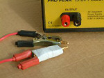
Another problem that comes up with a mains power supply is that some sort of method needs to be found to connect the charger’s power cable (which is invariably fitted with crocodile clips) to the 6mm output sockets of the PSU. One solution devised by one of my fellow club members was to use the clips to grip some male 6mm connectors, binding the crude assembly with tape. While this did work, it was clearly not an ideal solution!
Thinking the matter over, I decided to modify my own charger’s 12V power supply cable so that both problems were solved in one go. My solution involves cutting a short length from the middle of the supply cable, and then rejoining the breaks
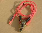
The
charger’s original
cable has been shortened,
and two alternative
adapter leads have
been made –
one lead retains the
original crocodile
clips, allowing connection
directly to a 12V
battery, and the other
much shorter lead
allows connection
to the 6mm sockets
of a power supply
output. No extra wire
is needed. |
with high quality connectors. By this means I created two alternative adapters to fit the shortened charger power supply cable:
1) A long adapter lead
which allows the charger
to be connected as designed,
to a 12V battery using the
original crocodile clips,
maintaining almost all of
the original full cable
length, and;
2) A much shorter adapter
lead which allows the charger
to be safely connected to
the PSU using a pair of
6mm gold connectors.
The photograph illustrates the idea, and shows the shortened main charger lead plus both adapter leads.
I’ve been really pleased with the convenience of this simple idea, which only took me about an hour to carry out. The work will of course invalidate the manufacturer’s guarantee but as my charger was more than a year old this didn’t matter to me. Should you choose to go this route as well, you do so entirely at your own risk. Of course, the work should only be done by someone suitably experienced in soldering and electrical matters.
Important
safety precautions
As supplied, the charger’s
power cable cannot be short
circuited. However, once
a break is introduced, this
does become a possibility.
For example, if the crocodile
clips are connected to a
12V supply battery, and
the other end of the cable
is left free, the free ends
could potentially touch
each other, resulting in
a short circuit.
The
negative wire was
shortened by about
1cm before assembly.
This results in the
male connector being
positioned behind
the female one. The
resulting safety gap
makes short circuits
much less likely. |
This could be disastrous, and just as serious as if the power wires of a large LiPo battery were allowed to touch each other, so a means has to be found to minimize this danger. So, before I describe how I carried out this project, I’ll first cover the important safety precautions necessary to deal with this issue. I’ve already developed ways to minimize the risk of short circuits with my batteries, so I used the same methods here:
Place
connectors at different
locations
By carefully trimming the
supply wires, the connectors
are located at slightly
different physical positions.
This greatly reduces the
chance of a short circuit
between the connectors of
either of the two adapter
leads. This physical spacing
is illustrated in the photo
below:
Make
sure the exposed (powered)
connector has negative polarity
The work is also planned
so that the exposed (male)
connector attached to the
crocodile clip equipped
adapter lead has a negative
polarity. In this way, if
this exposed connector end
did accidentally contact
the car’s bodywork
or engine (which will be
electrically negative),
it would be a harmless negative-to-negative
contact, rather than a dangerous
positive to negative contact
which could result in a
disastrous short circuit.
Add
a protective sleeve to the
exposed connector
If desired, an additional
protective sleeve can be
added to the exposed connector.
This precaution is detailed
later.
Always
connect an adapter lead
to the charger before connecting
to power
By simply making sure that
an adapter is connected
to the charger cable before
connecting to power, the
possibility of a ‘live’
exposed connector being
present is eliminated, so
no short circuit can occur.
This precaution is discussed
further towards the end
of this article.
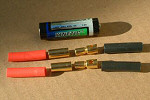
6mm
gold connectors are
ideal for this project.
The more common 4mm
size could also be
used. A pair of 4mm
male connectors (plugs)
are also required
to fit your power
supply’s output
sockets. The AA battery
is shown for size
comparison |
Materials required:
- Three pairs of suitable male/female connectors. I had three pairs of 6mm gold connectors available and these proved to be ideal for my project.
- One pair of male 4mm gold connectors to match the PSU output sockets.
- Solder, plus some suitable heatshrink sleeving.
Connector
notes
You don’t have to
use 6mm gold connectors,
but it’s important
that whatever type you do
choose, that they’re
of excellent quality and
a good, tight fit so they
can’t easily be accidentally
pulled apart in service.
Using shielded connectors
would be safer still than
using the 6mm type I chose.
Also, it might be wise to
consider selecting a different
type or size from whatever
you use with the rest of
your equipment to avoid
any possibility of inadvertently
connecting the modified
leads in any way other than
as intended.
Tools required
- Soldering iron and bit-cleaning equipment (e.g. damp sponge)
- A means of holding the connectors while they are soldered. One way to make a ‘helping hand’ is to glue a wooden clothes peg to a small block of wood.
- Sidecutters to cut and trim the power supply lead.
- Wire strippers to strip insulation off (a knife can also be used with care).
Soldering
safety
Soldering is potentially
dangerous and should always
be carried out with safety
in mind. Soldering produces
fumes which are best not
breathed in, so take care
to ensure adequate ventilation.
Also, use some form of eye
protection such as safety
glasses and take care to
wear clothes which cover
you fully in case of solder
spattering – solder
burns on the legs for example
are no fun! Also, its well
worth having a bowl of clean,
cold water ready nearby
to use in case of accidental
burns.
OK, let’s get started. Here’s how I carried out my project:
1. First, I drew a diagram of what I intended to do so I would have a plan to follow
|
Here’s
the diagram I used
to plan my own work.
You can print a copy
of this diagram by
right clicking and
selecting ‘print’. |

2. Before doing any work, I made sure the + and – leads would still be able to be identified after cutting them. In my case, a black line ran along one lead, clearly identifying it as the negative (-ve).
3. I then measured up the existing charger lead, and decided where I was going to cut it. My lead measured about 170cm (66in) before cutting.
4. Gathering my courage (!) I then cut the charger’s power supply lead. I chose the half-way mark, leaving me about 85cm (33in) still attached to the charger. I then took other the 85cm portion with the crocodile clips and laid it aside.
5. I also cut a further 15cm (6in) from the end of the lead still attached to the charger, so that the portion still attached to the charger measured about 70cm (27in). This was also put aside.
6. Next, I trimmed exactly 1cm from one wire of each of the three ends that would receive connectors (refer again to the diagram if this helps):
a) I cut 1cm from the +ve
wire from the cable still
attached to the charger
b) I cut 1cm off the -ve
wire of the crocodile clip
equipped lead.
c) I cut 1cm off one of
the -ve ends of the short
free length, leaving the
wires of the other end equal
in length.
The
completed 12V Battery
Adapter Lead. This
should always be connected
to the charger before
it is powered up,
eliminating the possibility
of exposed live connectors
touching each other. |
7. Now the soldering can begin. I took the free end of the crocodile clip equipped lead and soldered a pair of 6mm connectors to it, taking care to make sure that the that the negative (black) end is the one fitted to the male connector. Let’s call this completed adapter the 12V Battery Adapter Lead.
8. A second matching pair of 6mm connectors was then soldered to the free end of the lead still attached to the charger so that it could be reconnected to a 12V battery using the newly made 12V Battery Adapter Lead. Great care was taken to ensure that the correct polarity was maintained – in other words that the original connections had been re-established by the connectors.
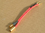
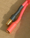
The
almost completed PSU
adapter lead. The
far end has a pair
of male 4mm connectors,
and the near end a
pair of 6mm connectors.
The last remaining
job is to fit a length
of red heat shrink
tubing to the female
connector. |
9. Having checked again that the polarity was correct, colour-coded heat shrink tubing was fitted to all four 6mm connectors, using red for positive and black for negative.
10. The third pair of 6mm connectors is then fitted to the unequally trimmed end of the short piece of lead. Before doing this, I made sure that when the connectors were in place that it would match the charger’s connections. I also made very sure that their polarity matched those of the 6mm connectors which I’d just fitted to the charger. Once completed, let’s call this short part the PSU adapter lead (see photo)
11. Finally, a pair of male 6mm gold connectors was fitted to the other end of the
|
The
almost completed adapter
leads. Two pieces
of red heat shrink
tube remain to be
fitted. |
short adapter lead to match the PSU. In this case, no difference in lead length was required. Lastly, red and black heat shrink tubing was added, again making certain that the polarity was correct.
13. One more job is to consider if you wish to fit an additional length of heat shrink over those connectors that could be involved in a short circuit. The photo illustrates this excellent idea:
14. A last, but most important job is to once more check everything very carefully before connecting power to the charger.
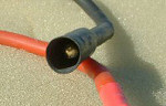
Here,
an additional length
of oversized sleeve
has been fitted to
a completed connector.
The sleeve is shrunk
at one end only, so
the additional sleeve
overhangs the exposed
connector, shrouding
it and reducing the
chance of a short
circuit to almost
nil. Its presence
makes joining the
connectors slightly
more cumbersome, but
this price is well
worth paying for the
increased safety. |
In use
There are only two issues
to take care of when using
the modified cables –
a short circuit can be avoided
simply by making sure that
one adapter lead or the
other is always connected
to my charger. This way,
there is no exposed end
to be involved in a short
circuit. The other issue
is remembering to take the
12V Battery Adapter Lead
when I go flying, and that’s
easily taken care of simply
by keeping it in my flight
box.
Conclusion
In use, the adapter leads
have proven to be very convenient.
No longer do I have the
problem of connecting the
charger to my PSU, nor do
I have an over-long charger
cable when using a workshop
PSU. Job done!