|
|||
|
|
|
||
| View Shopping Cart |
| Home |
| Guides Available |
| About the Author |
| FAQs |
| Testimonials |
| Articles |
| Contact Andrew |
| Terms & Conditions |
| Mailing List |
| Links |
 |
 |
More high quality information
absolutely free with every
Gibbs Guides newsletter. Sign
up now!
Setting up your model
Article by Andrew Gibbs
This part of the guide is particularly important, and offers a few pointers designed to maximise your chance of success. Depending on how they’re set up, two apparently identical training models can fly very differently, one being very easy to control yet the other very difficult. Let’s have a look now at some of the most important issues which can affect how easy a training model is to fly:
Set
up issue: Balance point
Correctly balancing your model is vital, and plenty of
models have been wrecked on their first flight because
this issue was overlooked. You should ensure your model
assumes a slightly nose down attitude when supported at
exactly the position indicated in the instructions. This
will usually be somewhere near 25 - 33 % chord position,
i.e. about one quarter to one third of the way back from
the wing’s leading edge.
Often, the flight battery can be moved to achieve the correct balance position (sometimes called centre of gravity, C of G or CG), but if this doesn't do the trick, weight will have to be added to nose or tail as appropriate. Add as much weight as needed to achieve the required balance position, even if you don’t like it! If the required additional weight seems excessive, you can always consider moving other items such as servos to new positions.
As the saying goes, heavy models have to fly a little faster, but tail heavy models won't fly for long at all! A model that has too rearward a balance point may be unstable and will be more responsive in pitch (elevator), even with limited control throws. If the balance point is sufficiently far rearward it will be extremely difficult to fly, even for an expert pilot. Conversely if the balance point is too far forward the model will again be difficult to fly and may lack sufficient elevator response.
Set
up issue: Lateral Balance
It’s also a good idea to check the model’s
lateral balance. To do this, ideally the model should
be checked when fully assembled. As an alternative, the
wings can be removed from the model and checked to ensure
one of them is not heavier than the other. This method
doesn't work so well with i.c. powered models which can
have the relatively heavy engine installed with the cylinder
well off to one side. If required, add weight to the light
wing tip. Firmly secured small nails can work well for
this purpose. Batteries can also be positioned off-centre
to reduce the need for any additional tip weight.
Set
up issue: Straight and true
A 'bent' model will never fly properly and this can add
enormously to the difficulty in leaning to fly, so it’s
really important that your model is assembled with its
flying surfaces straight and true. Time invested to ensure
your model is well built, especially in this regard will
be time well spent.
Wings
The wing must not be accidentally
warped. You can check for
warps by sighting along
the wing from each tip to
the root (centre). No twisting
should be seen, in other
words the wing tip should
be at the same angle as
the wing root all the way
along.
However, there’s one possible exception to this, and this involves a type of warp that is acceptable and even beneficial. This is known as ‘wash out’ and is present when the wing’s trailing edge can be seen to be slightly twisted upwards towards the tip. This gives the wing tip a lower angle of attack than the root, which can improve the model’s stall behaviour. The design of some models deliberately incorporates wash out.
Unintentional wash out, provided it’s not too severe can usually be accepted. In either case, both wings must have an equal degree of wash out. The opposite, ‘wash in’ is totally unacceptable and must be corrected before the model is flown.
Tail surfaces
Tail surfaces should also be unwarped. These are generally
made from sheet material and usually don’t warp
significantly. Surfaces should be at right angles, both
to each other and to the fuselage. Small errors here are
undesirable but they can be tolerated.
Set up issue: Control
surface centering
Make sure surfaces are set truly at neutral when the transmitter
sticks are centered, with the trims at neutral. This can
be checked using a ruler or with straight lengths of balsa
placed between the tail and the control surface in question.
Set up issue: Control surface movement
One of the classic ‘gotchas’ with model flying is to provide
too much movement of the control surfaces, the usual reasoning being that
more control must be a good thing. The reality is that training models
need very little control surface movement, and that crashes, especially
at the early stages of learning are much more likely to be a result of
over-controlling than from insufficient control authority. In over 30
years of flying RC models I’ve never experienced or even heard of
a crash resulting from insufficient control movement. Remember that free
flight models fly perfectly well with no pilot at all controlling them!
This is actually an important point to appreciate – a correctly
trimmed model (or full size) aeroplane will almost fly itself, and will
require very little pilot input.
The aim of early flights is simply to gain flight time without breaking the model, so tight manoeuvres requiring large control surface deflections have absolutely no part to play. As a guide, set the control surface movement exactly as the instruction manual for your model suggests. That said, in my opinion, sometimes the suggested control throws are substantially more than actually required. You’ll have to be the judge, but for a correctly set up model probably only 10-15 degrees of movement will be plenty for some models.
Set up issue: Control surface direction of movement
Make absolutely sure that the controls operate the correct way. Many full
size aircraft have been lost because of this seemingly obvious matter.
Elevator
With the elevator stick pulled towards you, the elevator should move up,
and vice versa.
Rudder
When right rudder is commanded at the transmitter, the rudder must move
to the right, as observed from the tail of the model.
Aileron
When right roll is demanded, the right aileron must move up, and the left
aileron downwards. It can be said that when standing behind the model
(imagine yourself in the cockpit), 'the aileron must travel up to meet
the stick'. The ailerons are particularly easy to get wrong, so take extra
care.
Set up issue: Exponential
If your RC outfit has an exponential function, this can be usefully used
to soften control responses about the neutral point, for example by adding
perhaps 30-50% exponential to rudder, elevator and aileron throws. Make
certain that you have set these set up in the correct sense. If you get
this the wrong way around the model may be very hard to control indeed!
For example, softened responses around the neutral stick position result from using positive (+ve) exponential with JR and Spectrum, but to get the same result with Futaba negative (–ve) exponential must be used. In both cases the 'expo' function works in the same way. The differences result only because each manufacturer uses their own convention. For those transmitters with a graphical representation of control response, simply make sure the flat part of the graph corresponds to the neutral stick position. In any case, its well worth carefully examining the control response by observing how the surfaces move in relation to the stick commands - do this before flying!
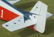
The
rudder and elevator
surfaces seen here
have been carefully
checked to make sure
they line up exactly
with the corresponding
fixed surfaces. |
Reduce 'slop'
To keep control movements reasonable without introducing excessive ‘slop’,
make sure you use the outermost hole on the control surface horns, and
one of the inner holes (as required) on the servo arm. For the same reason,
take care not to make the holes in the servo arms and control horns any
bigger than absolutely necessary.
Only after limiting overall movement in this way should you use the transmitter's travel volume function (ATV for Futaba) to reduce it down further if required.
Set up issue: Appropriate power
Training models need to be appropriately powered –
too little power will make the model hard to keep airborne,
while too much will make learning to fly much more difficult
for a beginner than it needs to be. Training models are
often fitted with much more power than they actually need.
The usual answer to this criticism is that the engine
can always be throttled back, but timely and appropriate
throttle management is a skill that only experience can
provide, which is something the beginner is very short
of. Excess power in a model produces a number of side
effects that the beginner will simply not be well equipped
to deal with and which will make control much harder compared
to an ideal model. These include the following, any of
which could allow a model to 'get ahead' of the pilot
flying it:
1. The model will be faster.
2. The rate of climb will be higher (perhaps much higher).
3. The control responses
will be sharper due to higher
airspeed and because of
the high speed prop wash
over the tail.
4. The asymmetric forces resulting from prop rotation
will be higher. Engine side thrust may not be enough and
the model may difficult to control during take off.
5. The model may have a
strong tendency to pitch
up sharply under full power,
possibly leading to a stall.
In short, excess power can transform a pleasant handling training model into a high performance machine requiring a high level of expertise and experience to handle successfully. Full sized basic training machines are always modestly powered and in my opinion RC training models should be as well.
Pleasingly, the issue of power is an area where electric power has an advantage – simply by fitting a smaller prop, the maximum output power of an electric motor can be reduced at will. So, choosing a larger than necessary motor for an electric training model can indeed be a sensible decision, provided that the model still remains sensibly powered by an appropriate choice of prop. Depending on the model type and power system efficiency, as little as 40 - 50 Watts per pound of model weight may be sufficient, and less may actually be better for the trainee pilot.
I’ll conclude this section with a specific recommendation - a training model is properly powered for a beginner when it will climb at a moderate rate at full power with the model in an appropriate state of trim, i.e. at not too fast an airspeed – just like a full size training aircraft.
Set
up issue: Undercarriage
(gear) and wheels
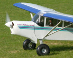
Whether
trainer or otherwise,
the undercarriage
must be adjusted if
necessary to ensure
good ground handling. |
It’s important that the ground handling of your model is good, otherwise every take off will be fraught with difficulty. All the wheels on your model must turn freely otherwise it may tend to veer towards the sticky wheel. You can expect to have to add a little right rudder on take off under high power conditions due to prop effects. However if the model won’t roll straight on the ground even at low power then the undercarriage will probably need adjusting. Don’t adjust the rudder control for this purpose, otherwise it will be permanently deflected in flight and cause other problems.
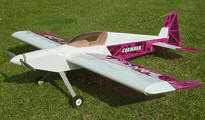
This model has been fitted
with large 'Tundra' tyres. |
Trainers sometimes benefit from having oversized wheels fitted. These will allow the model to handle bumpy ground more easily. Some full size light aircraft have enormous ‘tundra tyres’ fitted for this very reason. The extra aerodynamic drag of large wheels can be considerable and this will also help to keep the speed of the model down in flight.
Set
up issue: Installing the
RC gear correctly
This subject is far too
large to cover in detail
in this short article, but
a few of the most important
areas can be covered.
Receiver
Ideally the receiver will be wrapped in foam to protect
it from vibration. This precaution particularly applies
to non - 2.4 GHz equipment. In any case, make sure the
receiver is not too close to the ESC and any associated
power system wiring. Any UBEC unit (separate BEC) if fitted
should also be distant from the receiver and RC system
wiring.
Receiver
aerial
The receiver aerial must be undamaged and stretched out
to its full length, otherwise range may be compromised.
If your receiver has a long aerial (i.e. non - 2.4 GHz
systems), try to incorporate a vertical element, for example
routing it to the top of the fin as this will help improve
reception. Never run any aerial along or near to a metal
or carbon fibre component of significant size.
Wiring
Wiring must be arranged
so that plugs and sockets
cannot come apart in flight.
Include any extension leads
in your checks and remember
that vibration and G forces
will be present.
Keep RC wiring physically separate from the wiring or the power system – at least 50mm (2 inches) is ideal. This minimizes the chance of the power system causing interference to the RC system.
This
servo has been glued
in position using
a dab of hot glue. |
Servos
Where possible, servos should be installed with their rubber grommets
and screws. Some models call for servos to be installed directly into
moulded foam cavities, in which case this recommendation can be ignored.
Set up issue: Installing the power system correctly
As with the subject of RC installation, this subject is far too large
to cover in detail in this short article, but a few of the most important
areas can be covered.
Motor installation
The motor should be securely mounted. It must receive a plentiful supply
of cooling air. Ensure the prop driver is a firm, secure fit on the motor
shaft and that the prop nut is secure. The prop itself must be balanced.
ESC installation
The ESC should also be assured a plentiful supply of cooling air.
Don’t wrap it in foam as it needs airflow on all sides. The ESC
will emit radio interference, so Keep it spaced well away from the receiver
if at all possible. ESCs can be successfully mounted on the outside of
a fuselage – an ugly but practical solution.
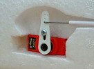
This
LiPo has been securely
retained using a strap.
|
Battery installation
Make sure the battery is securely retained so it cannot move in
flight. You'll need to arrange for a supply of cooling air to reach the
battery. LiPo batteries are physically a little delicate, so another idea
worth considering is to position a chunk of stiff foam such as polystyrene
in front of the battery to absorb some of the impact of a heavy landing.